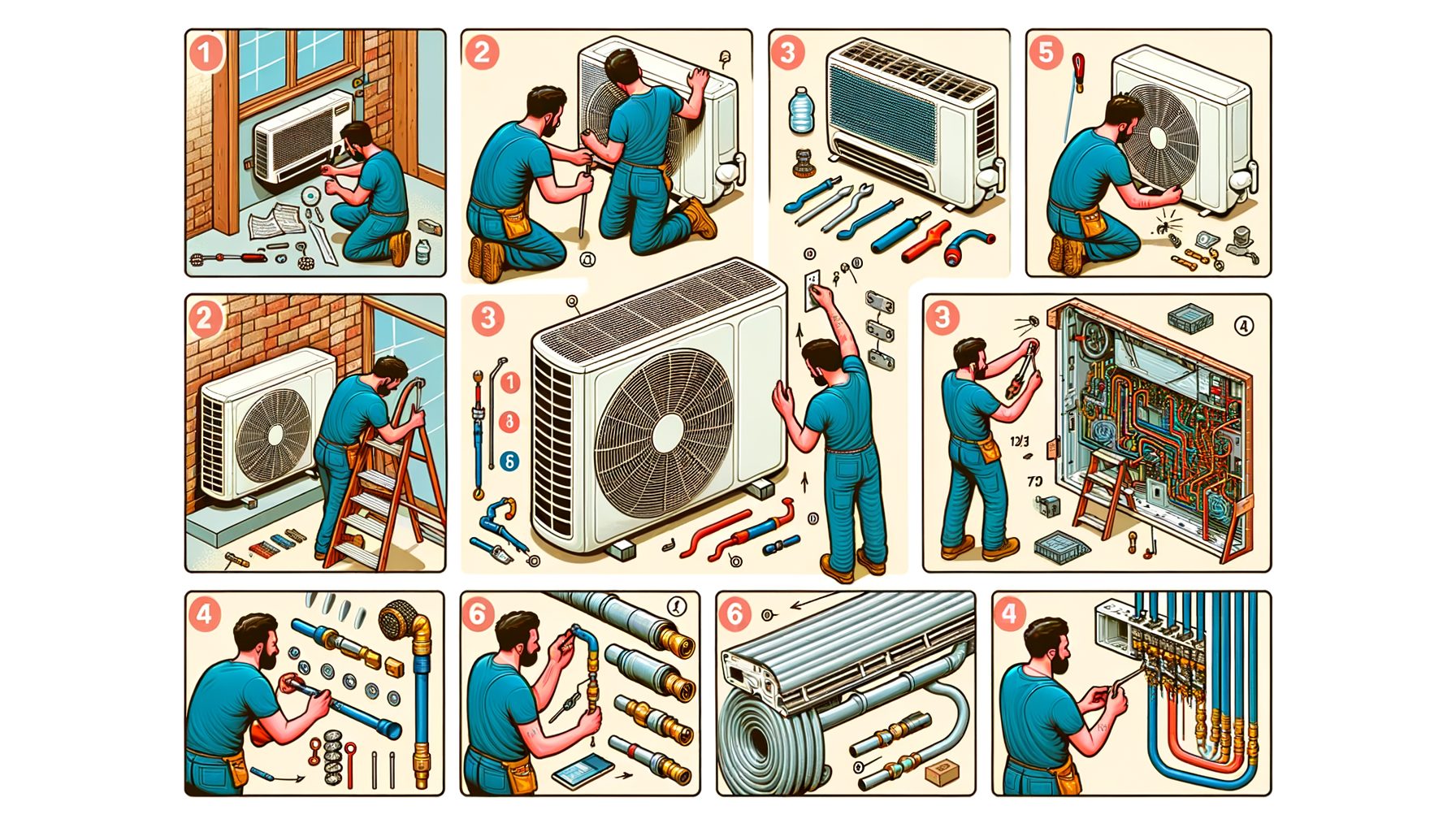
Installing a split AC can feel intimidating. Uncertainty is the main problem many homeowners and renters face: where to mount each unit, how to route the lines and drain without leaks, and how to vacuum and commission the system so it cools efficiently for years. A step-by-step split AC installation guide below demystifies the process. You’ll learn how to plan the site, mount the indoor unit, place the outdoor unit, connect refrigerant lines, pull a deep vacuum, wire the system, and verify performance. Even if you ultimately hire a licensed technician (recommended in many regions), understanding these steps helps you avoid costly mistakes, protect your warranty, and get better cooling for less energy.
What You Need Before You Start: Tools, Safety, and Smart Site Planning
Success starts with preparation. For most modern inverter mini-splits, you’ll need a level, stud finder, drill with a 65 mm (2.5 in) hole saw, masonry bit (if drilling concrete), vacuum pump, manifold gauges or a digital vacuum gauge, torque wrenches for flare nuts, flare tool (if making lines), a deburring tool, a nitrogen tank with regulator for pressure tests or purging, electrical screwdrivers, a multimeter, and weatherproof materials (UV-rated tape, line-set insulation, wall sleeve, and putty). Personal safety gear includes eye protection, gloves, ear protection, and a dust mask when drilling. If you’re in a region where refrigerant handling requires certification, plan for a licensed pro to handle refrigerant-side tasks. In the United States, for example, refrigerant work is regulated under EPA Section 608 (see the U.S. EPA guidance at epa.gov).
Plan the layout with efficiency and maintenance in mind. The indoor unit should blow air freely across the room without obstructions, ideally on an exterior wall for the shortest line set. Keep it away from heat sources and direct sun. The outdoor unit needs solid support, drainage away from the house, and adequate clearance for airflow and service access. Most manufacturers recommend at least 300 mm (12 in) on the sides and 600 mm (24 in) at the front, but check your model’s manual for exact numbers. Smart site planning shortens the copper line set, reduces the risk of condensate issues, and makes routine maintenance easier.
Capacity matters, too. For a typical well-insulated 20–25 m² room (215–270 ft²), a 9,000–12,000 BTU/h system often fits, but high ceilings, poor insulation, or hot climates may require upsizing. Search the AHRI Directory for certified performance data and SEER/HSPF/SEER2 ratings to estimate operating costs and climate suitability. Finally, confirm local codes and your manufacturer’s warranty terms. Many brands allow homeowner installation when performed to code but require commissioning by a licensed professional for the warranty to remain valid. A few hours of planning now can save days of rework later.
Indoor Unit Mounting and Line Routing: Clean, Level, and Leak‑Free
Begin with the indoor mounting plate. Use a stud finder and a spirit level to secure it to solid framing or appropriate anchors. The plate must be perfectly level; even a small tilt can cause condensate to pool or drip. Mark and drill a 65 mm (2.5 in) hole for the line set, drain, and control cable. Angle the hole slightly downward toward the exterior so the drain flows by gravity. A best-practice slope for the drain line is at least 6 mm per 300 mm (1/4 in per foot), or about 2%. If gravity drainage is not possible, plan a condensate pump rated for your unit’s flow rate, and route power to it per local electrical code.
Move on to the line set. If your system ships with pre-flared lines, inspect the flare faces for scratches and the nuts for roundness. If you need to cut and flare, keep cuts square, use a deburring tool to prevent copper shavings, and make clean, uniform flares. Add just enough refrigeration oil to the flare face if specified by your manufacturer. Slide the drain hose, control cable, and line set through the wall sleeve to protect the pipe insulation from abrasion. Seal around the sleeve with exterior putty or silicone to block rain, hot air, and insects.
Now hang the indoor unit on the plate and gently route the lines, avoiding tight bends that could kink the copper or collapse insulation. Keep the drain hose as the lowest point of the bundle so water cannot back up into the unit. Wrap the bundle with UV-rated tape to protect the insulation if the lines will be exposed to sunlight. Consistency is key here: a clean, level installation and a continuous downward slope on the drain are the top two factors that prevent water leaks inside the home. Pros often run a quick test by pouring a small cup of water into the drain pan before final closing to verify a steady flow outdoors—simple, but it catches errors early.
Outdoor Unit Placement, Refrigerant Lines, and Deep Vacuum
Set the outdoor unit on a solid, level surface—concrete pad, wall brackets, or anti-vibration feet on pavers. Keep it off soil to prevent settling and corrosion. Maintain clearances for airflow and service access; 300 mm (12 in) on sides, 150 mm (6 in) behind, and 600–900 mm (24–36 in) at the front are common guidelines; verify your model’s exact requirements. Avoid locations that trap hot air, such as alcoves, and ensure snow, leaves, or standing water won’t block the coil or fan.
Connect the refrigerant lines with care. Support the copper to avoid stress on the service valves. If you’re making flares, use a quality tool, and torque to the manufacturer’s spec to prevent leaks and micro-cracks. When brazing (less common on mini-splits with flares), purge with dry nitrogen to prevent internal oxidation. Pressure test the line set with nitrogen (often 2.0–3.1 MPa / 300–450 psi for R410A systems; follow the unit’s manual) and confirm no pressure drop. Then evacuate with a vacuum pump to 500 microns or lower, using a micron gauge. Close valves and watch for a rise; a stable hold test (for example, staying under 700 microns for 10 minutes) indicates tight, dry lines. Only then open the outdoor unit’s service valves to release the factory charge into the lines and indoor coil.
Pay attention to line length and vertical separation. Most units ship precharged for 5–7.5 m (16–25 ft) of line. If your run is longer, consult the manual for additional charge per meter and maximum allowed length/height. R410A and R32 are common refrigerants; both require clean, dry piping and correct charge for efficiency and compressor life. Skipping a deep vacuum is a top reason systems underperform or fail early. The table below summarizes widely used targets; always defer to your specific model’s manual.
| Item | Typical Value/Range | Notes |
|---|---|---|
| Indoor–outdoor clearance | Sides ≥ 300 mm; Front ≥ 600 mm | Check your model; more space improves serviceability |
| Drain slope | ≥ 2% (1/4 in per foot) | Gravity flow avoids indoor leaks |
| Nitrogen pressure test | ~2.0–3.1 MPa (300–450 psi) | Follow manufacturer; monitor for no drop |
| Deep vacuum target | ≤ 500 microns | Hold test: minimal rise, ideally ≤ 700 microns for 10 min |
| Flare torque (example) | 3/8 in: ~26–35 N·m | Use model’s spec; sizes vary |
Electrical Connections, Commissioning, and First Run
Wiring that’s safe and code-compliant protects people and equipment. Split ACs typically need a dedicated circuit sized to the unit’s MCA (Minimum Circuit Ampacity) and protected by the MOCP (Maximum Overcurrent Protection) on the nameplate. In many regions, you’ll run a weather-resistant disconnect near the outdoor unit and use appropriately sized copper conductors. Follow the wiring diagram on the indoor and outdoor covers for line, neutral, earth, and interconnect terminals. Tighten all lugs to spec, use proper bushings and strain relief, and verify ground continuity with a multimeter. If your system requires a separate communication cable, ensure it is rated for the environment and length, and route it away from power lines to minimize interference.
Double-check every step before startup: brackets level, drain slope verified, insulation intact, line set not rubbing on sharp edges, flares torqued, valves closed, nitrogen test complete, deep vacuum achieved, and electrical polarity correct. Open the service valves slowly to equalize pressure, then restore power. Many inverter systems perform an automatic test mode; if yours allows it, run the built-in self-check. Measure supply voltage at rest and under load, confirm the outdoor fan and compressor start smoothly, and use a probe thermometer or clamp thermocouple to observe indoor coil temperature drop. Within several minutes, you should see a steady delta-T across the coil (often 8–12°C or 15–22°F depending on humidity and mode).
Commissioning finishes with documentation. Record line length, added refrigerant (if any), torque values used, vacuum level achieved, and operating pressures/temperatures. Condensate discharge should be visible outside; listen for unusual vibrations and add anti-vibration pads if needed. Finally, review filter access and cleaning instructions with everyone who will use the system. According to the U.S. Department of Energy, proper installation and routine maintenance can reduce energy use by 20–30% compared to poor installations, which is a big win for comfort and bills. For energy-saving tips and sizing guidance, see Energy Saver resources from energy.gov.
FAQs: Split AC Installation
Q1: Can I install a split AC myself? A: Physically mounting the units and routing the drain is manageable for many DIYers, but refrigerant handling, pressure testing, and evacuation may be regulated where you live. In the U.S., EPA Section 608 certification is required for refrigerant service. Even if you do the prep, consider hiring a licensed HVAC technician for the refrigerant and final commissioning to protect performance and warranty.
Q2: How long should a typical installation take? A: A straightforward single-zone installation often takes 4–8 hours for an experienced pro, depending on wall material, line length, and electrical access. DIY prep can add time for drilling, mounting, and sealing, especially if you need to source tools like a vacuum pump. Complex runs, condensate pumps, or wall brackets can extend the job to a full day.
Q3: Do I need to add refrigerant if my line set is longer? A: Many units come precharged for 5–7.5 m (16–25 ft) of line. If your total line length exceeds that, the manual will specify how much to add per additional meter (for example, 20–30 g per meter for R410A on some models). Never guess; use a scale and follow your brand’s chart to avoid over- or under-charge, which can reduce efficiency and compressor life.
Q4: Why is a deep vacuum so important? A: Moisture and non-condensable gases inside the lines cause acid formation, freeze-ups at the metering device, noisy operation, and higher power draw. Pulling to 500 microns or lower and passing a hold test proves the system is dry and tight. Skipping this step is a leading cause of early failures and poor cooling, especially with high-pressure refrigerants like R410A and R32.
Q5: What clearances should I keep around the outdoor unit? A: Typical guidance is at least 300 mm (12 in) on sides, 150 mm (6 in) behind, and 600–900 mm (24–36 in) at the front for airflow and service. Keep the unit level, above standing water or snow levels, and free of obstructions like shrubs or fences. Always check your model’s manual; larger-capacity units may need more space.
Conclusion: Install With Confidence and Keep Your Cool
We began by addressing the main challenge of split AC installation: uncertainty about the right steps and standards. You learned how to plan the site, choose tools, and mount the indoor unit with a precise drain slope. You saw how to place the outdoor unit for quiet, efficient airflow, connect the line set with proper flares or brazing practices, pressure test with nitrogen, and pull a deep vacuum to 500 microns or better. You also walked through code-aware electrical connections and a practical commissioning checklist to validate performance on the first run. Together, these steps prevent the most common issues—water leaks, refrigerant leaks, noisy vibration, and high energy bills—and set the system up for long, efficient service.
Ready to act? Start with a simple plan: measure your room, choose an appropriately sized SEER2-rated unit, confirm electrical capacity, and mark an indoor location that allows a short, straight line run. Prepare tools, materials, and safety gear, and review your brand’s installation manual in detail. If your region requires certified refrigerant handling—or if you simply want the assurance—schedule a licensed HVAC technician to handle the pressure test, evacuation, and final charge verification. Well, here it is: a “hybrid” approach that saves time and money while keeping your warranty intact.
Next, optimize comfort and efficiency: maintain clean filters, keep the outdoor coil clear of debris, and check fasteners seasonally. Use manufacturer apps or thermostats to set schedules and eco modes. For deeper savings, review Energy Saver guidance from energy.gov and verify your model’s certified performance in the AHRI Directory. Share this guide with a friend who’s planning a project, bookmark it for your install day, and don’t hesitate to reach out to a professional for the critical parts of the job. With a clear plan, careful execution, and a proper vacuum and commissioning, you’ll enjoy quiet comfort and lower energy costs for years. Ready to make your home cooler, quieter, and more efficient—starting today?
Sources and helpful links:
• U.S. Environmental Protection Agency — Section 608 Refrigerant Management: https://www.epa.gov/section608
• U.S. Department of Energy, Energy Saver (Air Conditioning): https://www.energy.gov/energysaver/air-conditioning
• AHRI Directory (performance and efficiency ratings): https://www.ahridirectory.org/
• Mitsubishi Electric example installation resources: https://www.mitsubishicomfort.com/ and support manuals
• Daikin guides (regional): https://www.daikin.com/products/ac/support/